-
lvsota Platform
Equipment and
data integrationConnect multi-vendor equipment and existing systems through standard communication protocols and data interfaces. Use the data for monitoring, alerts, reports, and energy management.
Scroll to open the platform
View service details -
Structure revealed
Four areas of
system workInterfaces, data processing, operating rules, and system outputs form the basis for development, testing, and acceptance.
-
Continuous inspection
Project documents record each layer's responsibilities, inputs, and outputs for testing, maintenance, and adjustment.
01 / 04
Connector
Connect site equipment
Connect existing devices through industrial communication protocols and network interfaces, retaining the source, time, and communication quality of every reading.
-
02 / 04
Data Model
Standardize operating data
Align point names, units, and timestamps across vendors. Define shared fields for equipment status, power, load, battery level, and events.
-
03 / 04
Rules Engine
Apply operating boundaries
Apply safety limits, contract conditions, and deterministic rules. AI and optimization functions advise or act within approved boundaries.
-
04 / 04
API Gateway
Deliver system outputs
Deliver status, alerts, reports, and approved commands through one interface, keeping applications separate from device details.
-
System reassembled
System maintenance and
functional extensionsFunctions adapt as use develops. Data access and equipment control follow permissions.
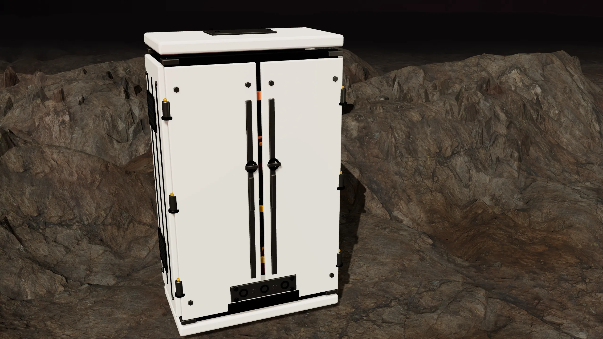
Equipment and data integration
starts with existing systems
Start with the equipment, interfaces, and data already on site. Energy and storage management are core applications, alongside equipment monitoring and operational workflows.
System outputs
System outputs and
management functions
A shared set of site data supports dashboards, reports, control, and analysis.
- 01
Dashboard
One view of equipment status, energy trends, and communication quality, so operators can spot a faulty circuit or lost signal.
- 02
Reports
Daily generation, demand changes, and alert events are kept and can be exported to spreadsheets as monthly energy and event working papers.
- 03
Control
Control commands pass permission levels and safety-rule checks, are issued after approval, and are logged. Protection applies on failure.
- 04
Agents
Once data has built up, add forecasting, diagnosis, and document retrieval as management needs require.
AI application planning
Each application is scoped around available data and operating needs.
- Reporting assistance
- Organizes energy, emissions, and management indicators into internal report drafts and working papers.
- Load forecasting
- Uses historical consumption and available external data to prepare forecasts for scheduling and management.
- Maintenance knowledge retrieval
- Searches equipment manuals and maintenance records. Qualified personnel perform field work under approved procedures.
Project delivery
System
implementation
- 01
Step 01
Inventory requirements
Document equipment, data sources, site scale, and management goals. - 02
Step 02
Connect and validate
Connect equipment or systems and check points, data quality, and agreed functions. - 03
Step 03
Build the system
Implement monitoring, asset records, inspections, alerts, reports, and other agreed functions. - 04
Step 04
Maintain and extend
Maintain and extend the system as needs change. New analysis, automation, or control functions reset data and permission conditions.
Project planning and
next steps
Discuss system implementation, data connection, or a proof of concept with lvsota.